19+ p&id drawing online
VP Online is your all-in-one online drawing solution. Opening a Drawing You can open a drawing in V-PID Process Designer only from the Project and Document Management dialog box.

Piping And Instrumentation Documents Instrumentation Tools Piping And Instrumentation Diagram P Id Diagram Mechanical Engineering Design
We provide data in DWG 2D and 3D DWG format.

. Once your drawing is complete you can share or present your designs in just a couple of clicks. As the name implies block diagrams represent any part component or system as a simple geometric shape with each block capable of representing a single component such as a relay or an entire system. Free online drawing application for all ages.
The intended use of the drawing dictates the level of detail provided by each block. When you place components and lines in your PID drawings each component contains data that links to the Data Manager. Custom drawing time in private rooms.
CUsersHrucha-004AppDataLocalAutodeskAutodesk AutoCAD Plant 3D 2022R241enuSupportinfocenterxml. One game consists of a few rounds in which every round someone has to draw their chosen word and others have to guess it to gain points. The PID is the primary schematic drawing used for.
The piping and instrumentation diagram PID is the detailed drawing of the process roadmap in an industrial facility. Intuitive editors and countless use cases More installs than all Confluence diagramming apps combined Best-in-class security Try it free Book a personal demo. Hydraulic reservoirs can be much more complex in terms of how the fluid is admitted to and removed from the tank.
In the Data Manager you can view data reports export them to a spreadsheet or a comma separated values CSV file and import them back into the program. How to Make Mood board. A drawing appears in V-PID Process Designer after it is opened.
We have all right and high-quality drawings and are ready to decorate your project. 4 PID Requirements 41 Introduction A PID shows information on piping fittings equipment instrumentation and process plant in a representative and sequential arrangement on the basis of product flow paths. How to Make a SWOT Diagram.
PID and PFD Symbols. How to Draw Block Diagram. You can use it as a flowchart maker network diagram software to create UML online as an ER diagram tool to design database schema to build BPMN online as a circuit diagram maker and more.
CAD is made in 4 projections. PID Design NX enables engineers to lay out piping and instrumentation diagrams PID in two dimensions while maintaining the design tied to the 3D space model. SmartDraws drawing software allows you to make designs from a Windows desktop a Mac or even your tablet or phone.
How to Create a Work Breakdown Structure. PIDs Piping Instrumentation Diagrams and PID Valve Symbol Library. Good Tips to Layout Your Drawing.
A piping and instrumentation diagram PID is a graphic representation of a process system that includes the piping vessels control valves instrumentation and other process components and equipment in the system. The PID layout does not necessarily reflect physical arrangements. Pumps and Turbine PID Symbols.
PID Symbols and Meanings. Skribblio is a free multiplayer drawing and guessing game. Autoclave auxostat axial fan back draft damper bag ball valve batch reactor butterfly valve check valve chemostat continuous batch reactor control valve cooled or heated pipe cooler cooling tower covered gas vent curved gas vent diaphragm.
Create professional flowcharts UML diagrams BPMN ArchiMate ER Diagrams DFD SWOT Venn org charts and mind map. PID Designer powers faster authoring common libraries between diagramming and 3D connectivity validation diagramming to 3D and equipment-level data management. There are few ISO and British standards available that provide symbols and best practices to draw PFD and PID such as ISA S51 BS 5070 and ISO 10628.
Up to 9 cash back AutoCAD P ID software allows you to create modify and manage schematic piping and instrumentation diagrams. Export to MS Office Vector PDF and Graphic Formats. These symbols are in Figure 20.
Enjoy the full range of features tools and symbols while at the office or in the field. The documents are developed accessed shared and modified throughout the plant lifecycle from design to operation. After closing the drawing V-It is advisable not to start V-PID Designer by double-clicking the file or using the.
This workflow describes how to design a PID drawing. To convey this information symbology conventions have been developed. PID symbols are a graphical representation of physical equipment that installed on the field.
The Plant SDK supports both products. Drawio can import vsdx Gliffy and Lucidchart files. While Starting the Auto Plant 3D 2022 it shows following errors in Log file.
AutoCAD Plant 3D adds 3D models including piping equipment support structures generation of isometric and orthographic drawings. Drawing pixel art is easier than ever while using Pixilart Easily create sprites and other retro style images with this drawing application Pixilart is an online pixel drawing application and social platform for creative minds who want to venture into the world of art games and programming. All our files are provided in Autocad 2007 and later.
Create digital artwork to share online and export to popular image formats JPEG PNG SVG and PDF. Plant 3D 2022 Freezes. It shows the interconnection of process equipment and the instrumentation used to control those related processes.
Please check out the new languages and report any spelling issues if you like. You can save your drawing as a PDF. We would like to show you a description here but the site wont allow us.
The following topic sequence provides links. The easiest way for Confluence teams to collaborate using diagrams Trust the 1 rated app on the Atlassian Marketplace. AutoCAD Plant 3D includes the features of AutoCAD P ID.
Block diagrams are the simplest type of drawing. Flowchart Maker and Online Diagram Software. Import a Picture in EdrawMax Import Visio Files into EdrawMax.
A PID is not drawn to scale. Pneumatic reservoirs are usually simple tanks and their symbology is usually some variation of the cylinder shown in Figure 20. If you do not receive an email within 10 minutes your email address may not be registered and you may need to create a new Wiley Online.
Sign-up for a FREE account today.

Pin On Drawing

How To Read Piping And Instrumentation Diagram P Id Piping And Instrumentation Diagram P Id Diagram Diagram

Piping And Instrumentation Diagram P Id Software Piping And Instrumentation Diagram P Id Diagram Id Software

Draw P Id Diagrams Online In The Browser With Google Docs P Id Diagram Diagram Online Drawing

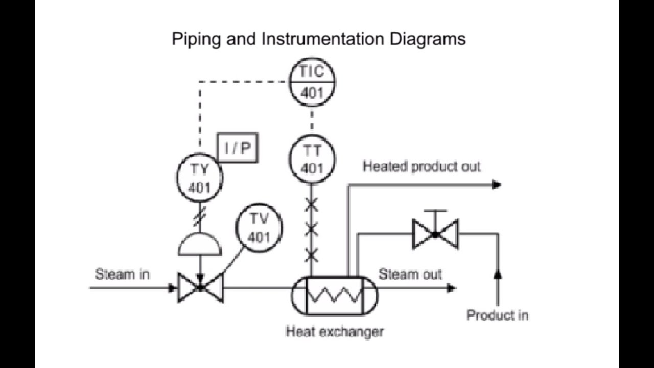
P Id Guidelines For Pumps Heat Exchangers Heat Exchanger P Id Diagram Heat

P Id Guidelines For Centrifugal Compressor Systems Centrifugal Compressor P Id Diagram Compressor

P Id 1 แผนภาพ 100 ความในใจ

Pin By Adam Jumblat On Chemical Engineering Distillation Piping And Instrumentation Diagram Information Engineering
Tank Level Control System Piping And Instrumentation Diagram Process Control Override

P Id Flow System Example P Id Diagram Piping And Instrumentation Diagram Example

What Is A P Id Diagram In Laymen S Term Realpars P Id Diagram Diagram Piping And Instrumentation Diagram

P Id Symbols With Letters Piping And Instrumentation Diagram Diagram P Id Diagram
How To Read Piping And Instrumentation Diagram P Id Piping And Instrumentation Diagram P Id Diagram Diagram

Coriolis Piping And Instrumentation Diagram Diagram P Id Diagram

P Id Flow System Example P Id Diagram Piping And Instrumentation Diagram Example